1050 aluminum plate can be considered for busbar and electrical conductor components because it belongs to the commercially pure aluminum series. However, an alloy name alone does not determine current rating. A useful specification must connect conductivity, section size, temperature rise, temper, joint design and the actual service environment.
Busbar Selection Starts With the Electrical System, Not Alloy Alone
Buyers often search for 1050 aluminum plate for busbars, “aluminum busbar vs copper” or a fixed ampacity chart. Those searches point to a real sourcing need, but a universal current table can be misleading. Heat generation depends on electrical resistance, while the final temperature also depends on ambient temperature, enclosure ventilation, bar orientation, spacing, surface condition, joint resistance and allowable temperature rise.
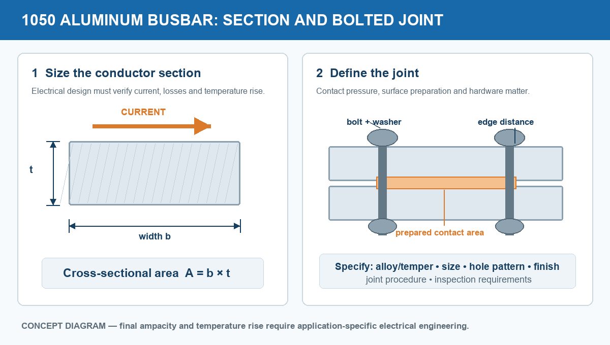
The first dimensional check is simple:
A larger area generally reduces resistance for a given length, but width and thickness are not always interchangeable. They affect exposed surface area, bending stiffness, available enclosure space, hole layout and heat dissipation differently. Final sizing should therefore follow the applicable electrical design method and equipment standard.
Aluminum Busbar vs Copper: Compare the Complete Design
| Comparison basis | What it means | Procurement implication |
|---|---|---|
| Equal cross-section | Copper generally provides lower electrical resistance than aluminum at the same dimensions. | Do not replace copper with the same-size aluminum bar without recalculation. |
| Equal electrical objective | An aluminum design commonly uses a larger section but benefits from lower density. | Compare total mass, envelope, supports and joints, not material price per kilogram alone. |
| Mechanical behavior | Strength, stiffness, thermal expansion and long-term joint pressure differ. | Verify support spacing, bolt system and thermal cycling. |
| Connection system | Oxide films, contact preparation and dissimilar-metal interfaces can dominate joint performance. | Specify mating-surface treatment, compatible hardware and installation procedure. |
Conductivity Is Important, but It Is Not Ampacity
Electrical resistance depends on material resistivity, conductor length, cross-sectional area and operating temperature. As the busbar warms, its resistance changes; at the same time, heat is removed by natural or forced convection and radiation. Alternating-current systems may also require attention to skin effect, proximity effect and phase spacing.
For that reason, the material certificate, a room-temperature conductivity value and a dimensional drawing are inputs to the calculation—not a substitute for it. The design engineer should define the permitted continuous current, short-circuit duty, maximum operating temperature, ambient conditions and enclosure arrangement before the buyer freezes the bar size.
Which 1050 Temper Should a Buyer Specify?
O temper for maximum forming flexibility
O temper is annealed and is normally the starting point when severe bending or forming dominates. Its lower strength can be a disadvantage where the bar must resist handling damage, support loads or sustained joint pressure.
H tempers for added strength
H12, H14 and other strain-hardened conditions offer different balances of strength and ductility. A harder temper can improve rigidity and handling, but tight bends, punching near edges or complex forming may need larger radii and process trials. State the full alloy-temper designation; “1050 aluminum” by itself is incomplete.
The final choice should match the product standard, minimum mechanical properties, bend geometry, hole-making route and the joint-load strategy. Do not assume that a temper selected for easy fabrication will also be best for long-term clamping behavior.
Joint Design Often Controls Field Performance
Aluminum rapidly forms a stable oxide film. That behavior supports corrosion resistance, but an uncontrolled film or contaminated mating surface can add electrical contact resistance. A reliable joint specification should address surface preparation, permitted time between preparation and assembly, contact compound where required, hardware compatibility, tightening method and inspection.
Bolted holes also need defined diameter, pitch, edge distance, burr limits and flat contact zones. Where aluminum connects to copper or plated components, the designer should evaluate galvanic compatibility, moisture exposure and the approved transition or plating system. Decorative coatings must not accidentally cover an electrical mating area unless the joint design specifically permits it.
Dimensions and Finish: What Belongs on the Drawing
| Drawing item | Why it matters |
|---|---|
| Width, thickness and cut length | Control conductor area, resistance, fit and weight. |
| Dimensional tolerances and flatness | Affect enclosure fit and the real contact area at joints. |
| Hole diameter, location and edge distance | Affect assembly, net section and local mechanical integrity. |
| Edge condition and burr limit | Reduce assembly damage, electrical-clearance risks and poor seating. |
| Mating-face finish or plating zone | Controls the interface used for current transfer. |
| Bends and grain direction, if applicable | Help the processor plan bend radii and part orientation. |
Review the 1050 aluminium plate product page, then send the alloy/temper, dimensions, quantity, standard, drawing, joint finish and required documentation for a like-for-like discussion.
A Practical RFQ Checklist
- Material: 1050 alloy and the required temper.
- Product form: plate, sheet, strip or machined busbar blank.
- Dimensions: width, thickness, length, tolerances and flatness.
- Fabrication: cutting, punching, drilling, bending, deburring and edge finish.
- Joint area: hole pattern, masking, cleaning, plating or other approved preparation.
- Technical basis: applicable material standard, drawing revision and inspection criteria.
- Commercial data: quantity, packaging, destination and required documents.
Frequently Asked Questions
Is 1050 aluminum good for busbars?
It can be a suitable commercially pure aluminum option when its conductivity, temper, dimensions, mechanical support and joint system meet the application. Suitability must be checked against the complete electrical and mechanical design.
Can an aluminum busbar use the same dimensions as copper?
Not by simple substitution. At equal cross-section, the materials do not have the same resistance, mass or mechanical behavior. The aluminum section, supports and connections require a fresh calculation.
Which 1050 temper is best?
There is no single best temper. O temper favors forming, while strain-hardened H tempers can provide more strength. Bend severity, rigidity, hole-making and joint pressure determine the useful balance.
Can anodizing or paint remain on a busbar joint?
Only if the approved joint design specifically allows it. Electrical mating faces normally need a defined conductive surface condition and controlled preparation; do not leave the requirement implicit.
What should be verified before ordering?
Confirm continuous and short-circuit current duties, allowable temperature rise, environment, section dimensions, temper, supports, joints, finish, product standard, inspection and documentation.
Technical basis: ASTM B209/B209M covers aluminum and aluminum-alloy flat sheet and plate; alloy and temper designations are governed by the applicable Aluminum Association/ANSI systems. Confirm the contractually required standard revision. This article is a procurement guide, not a substitute for electrical or mechanical design approval.
Post time: Oct-27-2026