How to Specify Drilled Holes in Aluminum Sheet and Plate
A drilled hole is not defined by diameter alone. Aluminum alloy and temper, material thickness, tool condition, work support, feed, chip evacuation and the required edge condition all affect the finished hole. A useful drawing or RFQ should state the hole geometry, tolerance, burr or edge-break requirement, applicable faces and the inspection method.
Quick answer: for repeatable hole quality, specify the aluminum product and temper, finished hole diameter and tolerance, hole location, entry and exit faces, countersink or chamfer geometry, acceptable burr or edge break, surface-protection limits and whether dimensions apply before or after finishing. Do not rely on a general note such as “deburr all edges” when assembly, sealing or fatigue performance depends on the edge.
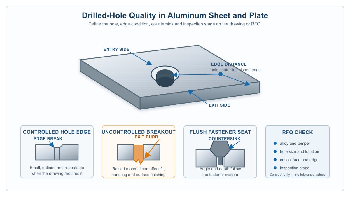
Why Aluminum Hole Quality Varies
Aluminum is available in different alloy families, tempers and product forms. A soft annealed sheet may deform or form a larger exit burr if it is poorly supported. A harder or strain-hardened product can produce a different chip and edge response. Thick plate also behaves differently from thin sheet because the tool remains engaged longer and chip evacuation becomes more important.
The purchase description should therefore identify the actual material, for example 5052-H32 sheet or 6061-T651 plate, instead of using only the word “aluminum.” The drawing should also distinguish through holes, blind holes, tapped holes, reamed holes and countersunk holes. Each feature has a different inspection requirement.
| Input | Why it matters | What to state |
|---|---|---|
| Alloy and temper | Affects hardness, chip formation and deformation tendency | Exact alloy, temper and product form |
| Thickness | Changes tool engagement, support and exit behavior | Nominal thickness and tolerance basis |
| Hole function | Clearance, location and edge finish depend on assembly use | Fastener, locating pin, fluid passage or access hole |
| Surface condition | Film, coating or cosmetic faces may be damaged by clamping or chips | Protected face, film-removal stage and finish exclusions |
Entry Burr, Exit Burr and Edge Break
A burr is material that remains outside the intended edge after drilling or another cutting operation. The entry side may show a small raised lip, but the exit side often needs more attention because the remaining material becomes thin before the tool breaks through. Poor backing, excessive tool wear, unsuitable process conditions or insufficient support can increase breakout and burr formation.
“Remove burrs” and “break sharp edges” are not identical instructions. Burr removal eliminates loose or projecting material. An edge break deliberately creates a small chamfer or radius. If the edge-break size affects sealing, fastener seating, fatigue life or appearance, define it on the drawing. ISO 13715 provides a system for indicating edges of undefined shape. If a geometrically defined chamfer or radius is required, dimension that geometry directly.
When a general deburr note is not enough
- a sealing face must remain flat and free from abrasive rollover;
- a countersunk fastener must sit flush to a defined condition;
- a fatigue-sensitive hole needs controlled edge geometry;
- a cosmetic face cannot accept visible scratches or witness marks;
- only one side may be accessible for secondary finishing.
Hole Diameter, Roundness and Location
A nominal drill size does not guarantee the finished hole diameter. Runout, tool wear, machine condition, material movement and post-processing can change the result. For a clearance hole, state the finished diameter and tolerance. For a locating or bearing feature, the drawing may require drilling followed by reaming, boring or another finishing method.
Hole location should be controlled from defined datums rather than from a rough saw-cut edge. If the blank will be trimmed after drilling, identify which operation establishes the final datum. Also state whether inspection is performed before or after anodizing, coating or another surface treatment, because added thickness or masking can affect the measured opening.
Countersinks and Flush Fasteners
A countersink must match the fastener system and drawing. The included angle, major diameter or depth, concentricity and allowed flushness should be defined. A drawing that only says “countersink” leaves several acceptance questions unresolved. Excessive depth can reduce the remaining sheet thickness around the hole, while insufficient depth prevents the fastener head from seating as intended.
Thin-sheet caution: confirm that the selected fastener and countersink geometry are compatible with the available sheet thickness. If the geometry removes too much material, the design may need a different fastener, a formed feature, a local reinforcement or another joint arrangement. The material supplier should not infer this decision from the sheet thickness alone.
Edge Distance and Hole Spacing
Edge distance is normally measured from the hole center to the relevant finished edge, but the drawing should make the datum clear. Minimum edge distance and spacing are design decisions that depend on the alloy-temper, thickness, load direction, joint type, fastener system and governing design code. A material supplier cannot replace the structural or product-design calculation with a universal rule.
For quotation, indicate whether dimensions refer to the final machined edge or the incoming blank edge. If holes are close to a bend, also provide bend location, inside radius, forming sequence and the required hole position after forming. Drilling before and after bending can produce different results.
How to Inspect Drilled Holes
| Characteristic | Typical verification approach | RFQ clarification |
|---|---|---|
| Diameter | Appropriate plug, bore or coordinate measurement | Finished size, tolerance and inspection stage |
| Location | Measurement from drawing datums | Datum scheme and sampling plan |
| Burr or edge break | Visual, tactile or measured check as specified | Maximum condition, applicable faces and exclusions |
| Countersink | Angle/diameter gauge or agreed fastener fit check | Angle, depth or major diameter and flushness criterion |
| Surface damage | Visual check under agreed lighting and handling condition | Cosmetic face, film condition and allowed witness marks |
RFQ Checklist for Aluminum Sheet and Plate with Holes
- alloy, temper, product form and governing material specification;
- thickness, width, length, quantity and blank tolerances;
- drawing revision, units, datums and coordinate origin;
- hole type, finished diameter, tolerance, quantity and location;
- entry side, exit side and any one-sided processing restriction;
- countersink angle, major diameter or depth, and flushness criterion;
- burr, chamfer, radius or edge-break requirement and applicable edges;
- surface finish, protective film, cosmetic face and handling limits;
- inspection method, sampling plan, documentation and acceptance stage;
- whether drilling occurs before or after bending, anodizing or coating.
Frequently Asked Questions
Which aluminum alloy is easiest to drill?
There is no single answer for every hole and finish. Free-machining alloys can offer favorable chip control, while common sheet and plate alloys are selected for forming, corrosion resistance, strength or welding. Choose the material for the finished part first, then qualify the hole-making process for that alloy, temper and thickness.
Why is the burr larger on the exit side?
As the drill approaches breakthrough, the remaining material becomes thin and can deform before it is fully cut. Work support, tool condition and process stability influence the result. The drawing should state which side is critical and how the finished edge will be accepted.
Should holes be drilled before or after anodizing?
That depends on dimensional, corrosion and cosmetic requirements. Drilling after finishing can expose bare metal and damage the surface. Drilling before finishing may change the measured opening or require masking. State the sequence and the inspection stage on the drawing or purchase order.
Is “deburr all holes” sufficient?
It may be sufficient for noncritical handling edges, but it is not enough when the edge geometry affects fit, sealing, fatigue, coating or appearance. In those cases define the permitted burr, chamfer or radius and identify the applicable faces.
Prepare a Clear Aluminum Sheet or Plate Enquiry
Review the SASA ALUMINUM sheet and plate range, then send the alloy-temper, thickness, blank size, drawing revision, hole and countersink requirements, surface condition and inspection criteria.
Post time: Oct-28-2026